IC9700 Send Splitter
I've recently got myself this lovely new radio, it's a great bit of kit and i'm really impressed so far :-)
The main issue i found was that there is only one output pin on the ACC 8-pin DIN socket to control external amps/lna's for all three bands.
This was a show stopper for initial use here as i had to manually change control cables over when i swapped bands, sooner or later i would end up firing a few watts into the back of one of the LNA's... not a good idea!
The solution i have come up with could be much simpler but this was the easiest way for others to repeat without a special board made up.. Maybe someone else can do that and use a cheap micro controller at the same time ;-)
Arduino boards are readily available and easy to program so it seemed like the best option for now.
I used an Arduino Nano board programmed up to send the command 0x25,0x00 to the radio using the Remote data socket on the radio.
This requests the current main band frequency from the radio (the top displayed frequency which is the Tx freq), it then enables one of three pins on the output of the arduino depending which freq band is selected.
These pins drive three open collector NPN transistors who's bases are tied together and route back to the single SEND pin on the radio's ACC socked (8-pin DIN, pin 3) allowing three separate outputs to control an amplifier on each band separately.
Please note that this does not work when you are using PC software to control the rig via CI-V interface at the same time, using wsjtx here the PC software looses comms with the radio. Looking into the possibility of using the LAN port to read the Tx frequency instead if that is possible!
Baud rate must be set to 19200 with the example code below, Menu > SET > Connectors > CI-V > CI-V Baud Rate
You will need 1x Arduino Nano, Uno, or whatever you have - minor code changes for pins between arduino boards.
5x General purpose NPN transistor
A few resistors, no values are particularly critical, just use the closest you have.
Here is the schematic:
IC9700 Send Splitter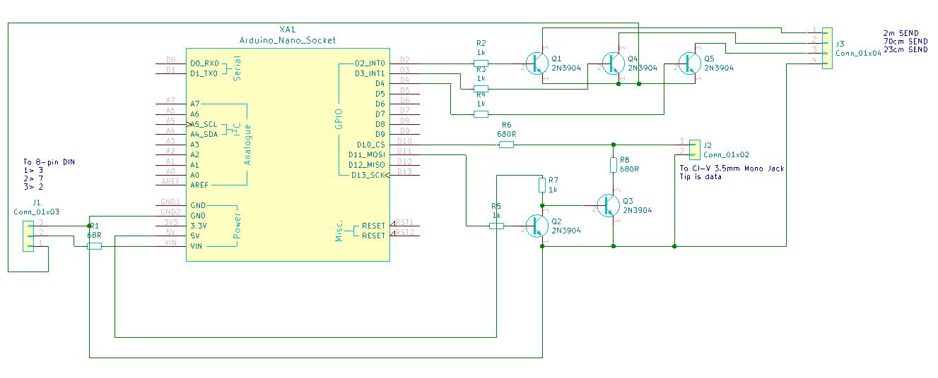
Current development box - all ok so far!
SEND Splitter Box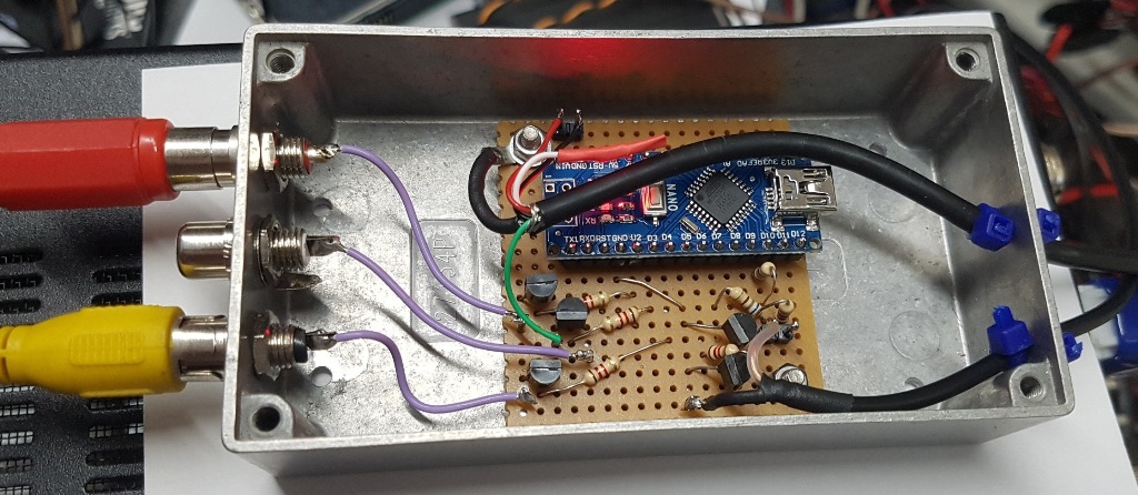
Here is the arduino code:
IC9700_PTT_SWITCH.ino
Some comments:
1 - You can reduce the component count if you use another SoftwareSerial port with inversion option, just for the Tx pin.
2 - Output current of the open collector outputs is still limited to the radio output. You could buffer this if you feel you need some more isolation.
Use at your own risk, i won't take any responsibility for radio damage here.


