Chirp Sounders
HF Chirp Sounders
A recent project was monitoring HF Chirp Sounders...
For the last few weeks I have been looking back into HF Propagation sounders, not because I want to use HF bands but just for the fun of it really!
These sounders use frequencies from 2-30MHz and are located at various sites around the world. Conditions at present (Feb 09) are very poor and only a few sounders are received on a daily basis. For monitoring i'm using an indoor 20m dipole and an ICOM 706mkIIG."
These HF Sounders are easiest thought of as a linear VCO swept from 2-30MHz, amplified and fed into an antenna but i'm sure they are a little more complex that this!! The sweep is usually in sync with a stable time standard but this is not the case for all sites.
The sounders usually have a sweep rate of 100KHz/second and cycle over various time periods so they don't not overlap with other sounders.
Common period times i have seen are 300,600,720,900 seconds. These time periods are the cycle time of the sounders, each sounder starts from 0MHz (but only transmits above 2MHz) at the beginning of each time period. Each sounder is offset from the zero point so that different sounders do not start at the same time. This offset is called the 'chirp time'
For example here we have a sounder with a period of 300 seconds and a chirp time of 78 seconds (UK Inskip sounder)
Starting at midnight the 300 second periods would begin, the sounder would start from 0MHz when the period gets 78 seconds through (chirp time) i.e. 1 minute 18 seconds past midnight and would finish at 30MHz at 6 minutes 18 Seconds past midnight at which point it will restart back to 0MHz for the next sweep.
This applies to all the sounders I have heard so far and makes it possible to calculate when a specific sounder will be on a certain frequency. For sounders with a period of 600 or above and going by the fact that they usually sweep at 100KHz/second then it is likely that it will only be active for the first 300 seconds of the period and switch off for the rest.
Receiving chirps on your HF radio
Receiving these sounders on any modern radio is quite easy but requires some thought and an understanding of what we are actually trying to do, timing is the main issue with identifying a particular sounder. It could be done with pen and paper but there is a piece of software that can do this for you called ChirpView
Chirpview uses a 1PPS time standard (MSF/GPS) to lock the software clock to for accurate timing, it also uses the audio from the receiver to listen for the 'chirps'.
First your receiver is set to some HF frequency in USB mode and this frequency is entered into the ChirpView program.
As the sounder passes through the pass band of the receiver from LF>HF very quickly you hear a 'chirp', the software detects this and after a few chirps it determines the period and chirp time automatically for you by using time and receive frequency in the calculation, there is a small database of the known sounders available as a reference (Sounders.txt)
"Sounders I have heard are:
100KHz/s rate
300:20 - France QRT
300:78 - UK Inskip QRT
300:235 - Cyprus
300:240 - Cyprus
720:640 - stateside somewhere *varying chirptimes
900:85 - St Eval SW England QRT
900:580 - Finland, Sodankyl?
900:880 - ?
50KHz/s rate
300:116 - Holland, Havelte
500KHz/s rate
60:54 - Sodankyl?, Finland ?
Once you have identified a sounder's Period and Chirp time it is possible to track the sounder across the HF spectrum and by doing this you can find out which bands are open to where the sounder is located and it is also possible to tell the propagation type it is using.
There are two programs available for CAT control of HF Radio's, one for Icom and one for Kenwoord but there was nothing for other radio's.
I decided to make a program that could be used with most radios by using HamRadioDeluxe as the interface, HamRadioDeluxe can control most HF radio's and has remote control facilities so it is possible to set the frequency from another program..
The software works by stepping the frequency upwards in 100KHz steps following the sounder up the bands, the radio is set slightly ahead of the sounder as it waits for the sounder to go through the pass band before going to the next 100KHz. The software has Period and Chirp time input so you can follow any of the sounders you have detected. It also has an offset to correct for the delay in writing the frequency to the radio.
You need to set your pc clock to within 1second of atomic clock but that's easy with the use of time sync software like dimension4 etc..
HRDStepper V1.11 - Now working with HRD V5
Added 50KHz/s and 500KHz/s souder settings, updated to use DDE link to HRD.
Download here - Like the last version please use at your own risk, my programming skills have not improved much!
My ORIGINAL HRDStepper program can be downloaded here
ChirpView can be downloaded from here
Other links for Chirp sounder information:
G3CWI
ZL1BPU
G3PLX and G0TJZ Chirp Sounder information can be found here
Building a Dedicated Chirp Receiver
Since having a go at the software to step my radio to make ionograms I saw what some other stations were doing and generating much more detailed ionograms. These ionograms don't really show any more information but are a lot nicer to look at. I was also quite interested in how it was done using a custom receiver for the job.
The setup for most home-brew Chirp Receivers is like this?
The IF is somewhere above the maximum frequency of the sounder's range (>30MHz) The LO sweeps up in frequency at the same rate as the sounder.
I'm currently using my HF receiver as the IF on 33MHz. The LO is generated with a DDS chip the AD9854 and uses the same 30MHz oscillator from the receiver as the reference, the DDS multiplier is set to 5 to get 150MHz. DDS chips require at oscillator of at least double the highest output frequency required.
The input of the receiver goes through a 30MHz low pass filter and a simple mmic pre-amp then into an SBL-1 mixer with the DDS LO and a MAR-6 mmic on the output. The IF is very simply filtered at 33MHz and then out to the HF set.
The reason we use the DDS for the LO is because it has a feature that enables it to do very linear frequency sweeps with a lot less effort. The frequency setting is connected to a counter that increments the frequency by a pre-set step size on each oscillator clock cycle. This counter can be triggered using one of the control pins on the chip.
So to do a sweep this is what we do:
1: The chip is reset to take all registers to their default settings
2: The chip is put into the sweep mode
3: The start/stop frequencies are loaded in
4: Wait until the trigger pin is pulsed in sync with the sounder that we are trying to monitor then start the sweep.
In my receiver I'm using the 1pps output of my GPS receiver connected to the trigger pin permanently and then update the chip in the second before I want it to start sweeping, the idea was from another station and seems to work quite well. I modified someone else's Visual Basic code that was using the AD9854 to make it all work coordinated with time and the chirp times of the different sounders.
The receiver audio is connected to the PC soundcard and then plotted on a waterfall with SpectrumLab. I have used the tcp-ip interface of SpectrumLab to refresh the screen at the start of a sweep and add the frequency markers along the bottom, the commands are sent from the DDS software.
I'm not going to put the code for the DDS on here for now as it's still very buggy and the person who wrote the original part for the AD9854 would probably not be too happy about me using it!
Work is in progress for a buggy software release though! Nov 2011
If you are interested in having a go I would encourage you to try and make your own software as it's very educational regarding setting up DDS chip's etc, I learned a lot from the process and would not hesitate using a DDS for other projects like I used to! If not then I'm sure some of the others on the chips mailing list would be happy to share some of their software with you.
Here is the system, not very tidy but it works!
ChirpRx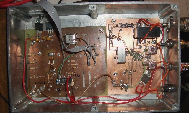
The DDS on the left is a copy of this design here but with PC control rather than PIC.
The right is the Mxer and IF filter with some switching.
The DDS chip (on the underside of the board) is quite a challenge to solder correctly if you have not done SMD work before and also quite expensive now!!
Make sure you heatsink the chip well because if you turn all the features on in the code by accident it draws over 1A from supply!
Normal operating current is about 450mA
DDS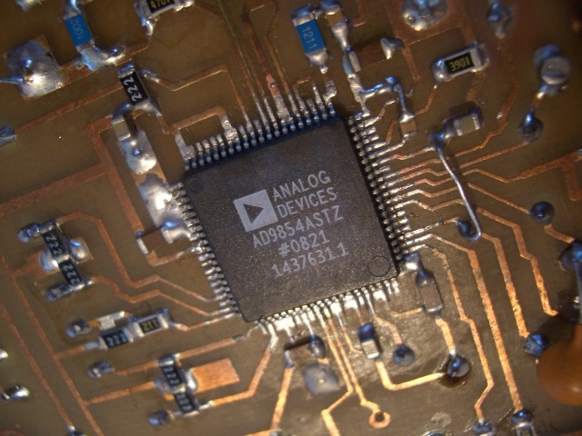
Some examples of the spectrum plots i have received with the dedicated Chirp Receiver..
Cyprus - 300:250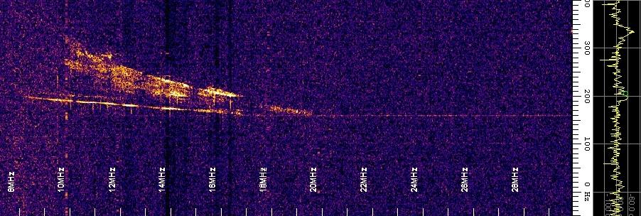
Signals from Inskip, Uk - 300:78 NOW QRT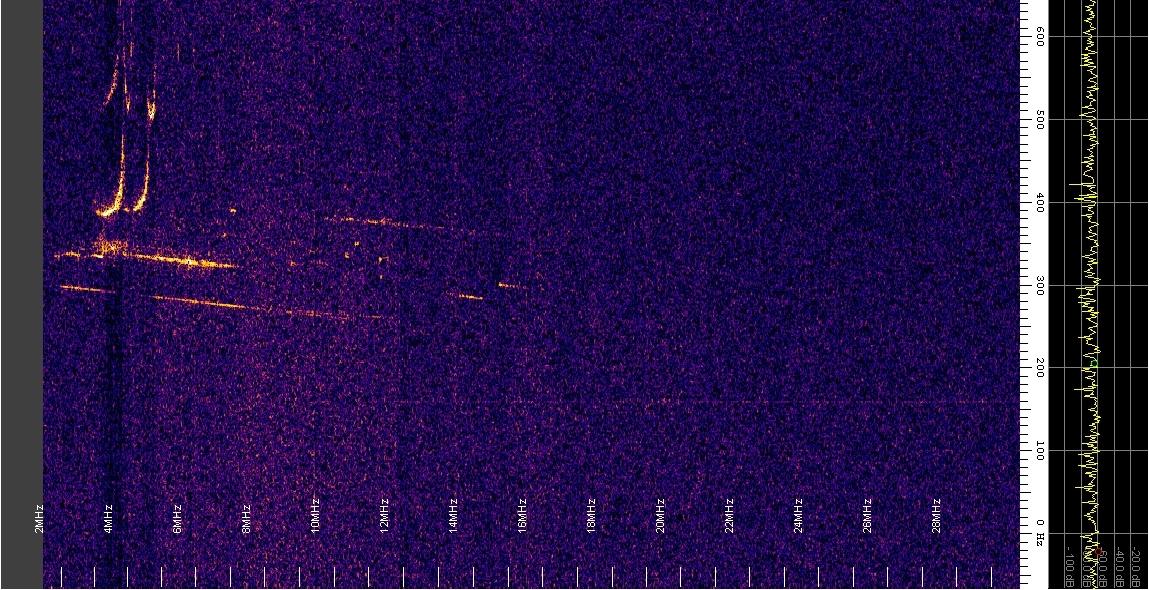
Another from Cyprus on 30th Oct 2011 with nice propagation!


