The LM2596 switching regulator boards that are easily found all over the place now make nice negative supplies for various bits of kit up to an amp or so.
See the datasheet for the schematic, here is the circuit board mod to take it from Positive to Negative output.
LM2596 Data
The PCB layouts may vary so watch out!
They are also very sensitive to ESD it seems during/after this mod, so proceed at your own risk!
There are now some 200mA negative voltage switching modules on ebay which maybe easier to use!
Two pcb cuts required:
Bottom - remove connection to LM2596 tab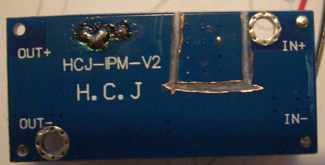
Top - remove connection to VR pins (right two)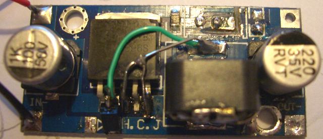
Wiring mods:
Diode removed from Pin 2 to ground and now from pin2 to -V output.
Pin 5 lifted and connected to -V output.
Pin 3 connected to -V output.
Remove the voltage adjuster pot and disconnect the right two pins from other tracks as seen in second photo.
Two pins on back of VR are soldered to ground - see pic.
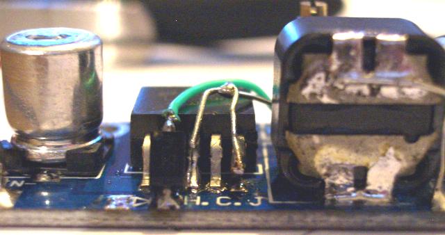
Inductor re-positioned on end and link to ground.
The output Electrolytic needs to be rotated around for the now reverse polarity output.
With this modification the inrush current at power on is a few Amps so if you have a limiting supply then the device may self destruct!
You can sequence the power on with the circuit in the datasheet for bootstrapping (8.3.3) and this will help.
Inductor position/connection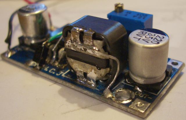
LM2596 pin connections