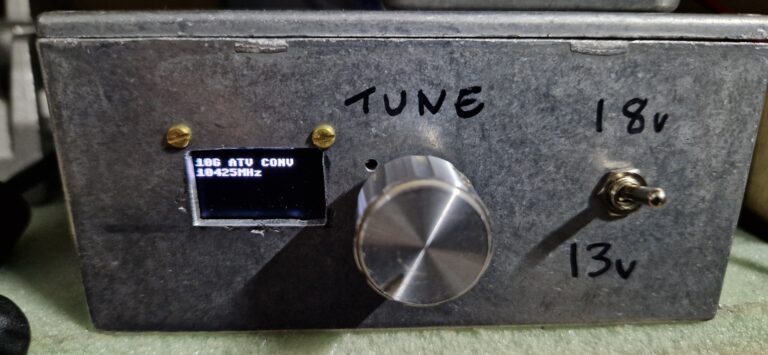
ATV Using an LNB to receive 10GHz ATV on my IC905 Rob January 17, 2025 I made a converter to be able to see...Read More
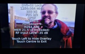
DATV GB3YT via Tropo to NY Moors Rob January 17, 2025 YT was coming in fairly weak but stable to...Read More
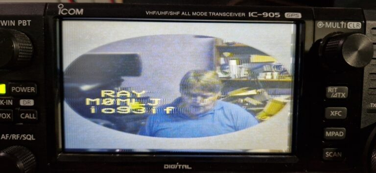
ATV 10GHz Analogue ATV Dx! Rob January 17, 2025 Here’s Ray M0MLJ’s signal on 10GHz 16/1/25 using 1m...Read More