The Receiver part of the system is also quite simple in regards to what is required but a lot of work has been done in the past to make it optimised for the very weak light we are looking to detect.
I'm using the KA7AOI V3 design which seems to be the best performer, The K3PGP design is slightly better for lower frequencies <1KHz but I have not found that much difference in my tests.
The VK7MJ design appears to be best for subcarrier work like I was using previously.
All of the circuits can be found herehttp://www.modulatedlight.org/optical_comms/optical_rx1.html
The Rx circuit should be built into a metal box for screening to reduce light and reduce 50Hz getting in. Most of my designs have been lacking in this department but I've still managed good results though!
The Rx uses a 25x25cm fresnel lens from 3dlens.com, I purchased it well before the tests in 2010, since then the A4 size page magnifiers have been used to great extent.
The lens is in a wooden box and painted matt black inside to try reduce reflections.
The Tx or Rx 'head' is built to fit the port on the rear of the lens box, this is regular gutter drain pipe tube at 60mm but the size is not critical. This allows us to rotate or slide the Rx or Tx diode into the focus of the lens.
On top of the lens box I have a 50mm finder scope from my telescope. This is quite an essential part of the system and is extremely useful to aid alignment of the lens on the horizon then the direction required.
The angle of view from the finder scope is 5degrees, this helps us when there is no visible signal (NLOS) and we need to line up using point of reference many deg away from where we need to point.
In one of my tests Bilsdale TV Transmitting mast lighting was used as a reference.
RxLensBox1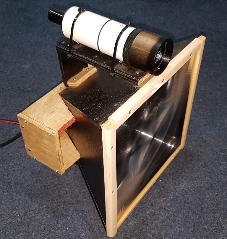
RxLensBox2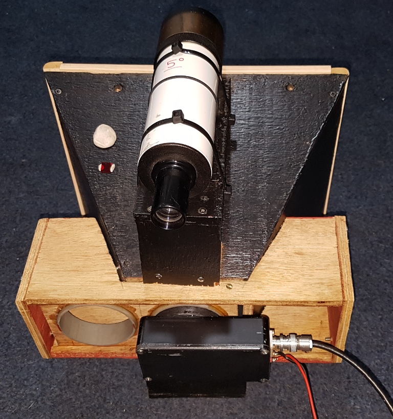
For all the longer distance tests made back in 2010 I used an SFH213 photodiode which has a smaller capture area so we end up with a narrower beam to get a little more overall gain.
The focus spot of the fresnel is much smaler than the original BPW34 hence the smaller diode used.
The larger area of the BPW34 is of benefit for NLOS comms as the area of scattered light is larger, the VK7 stations used an array of 36 BPW34's to increase rx capture angle when using their large fresenel lenses.
BPW34 *4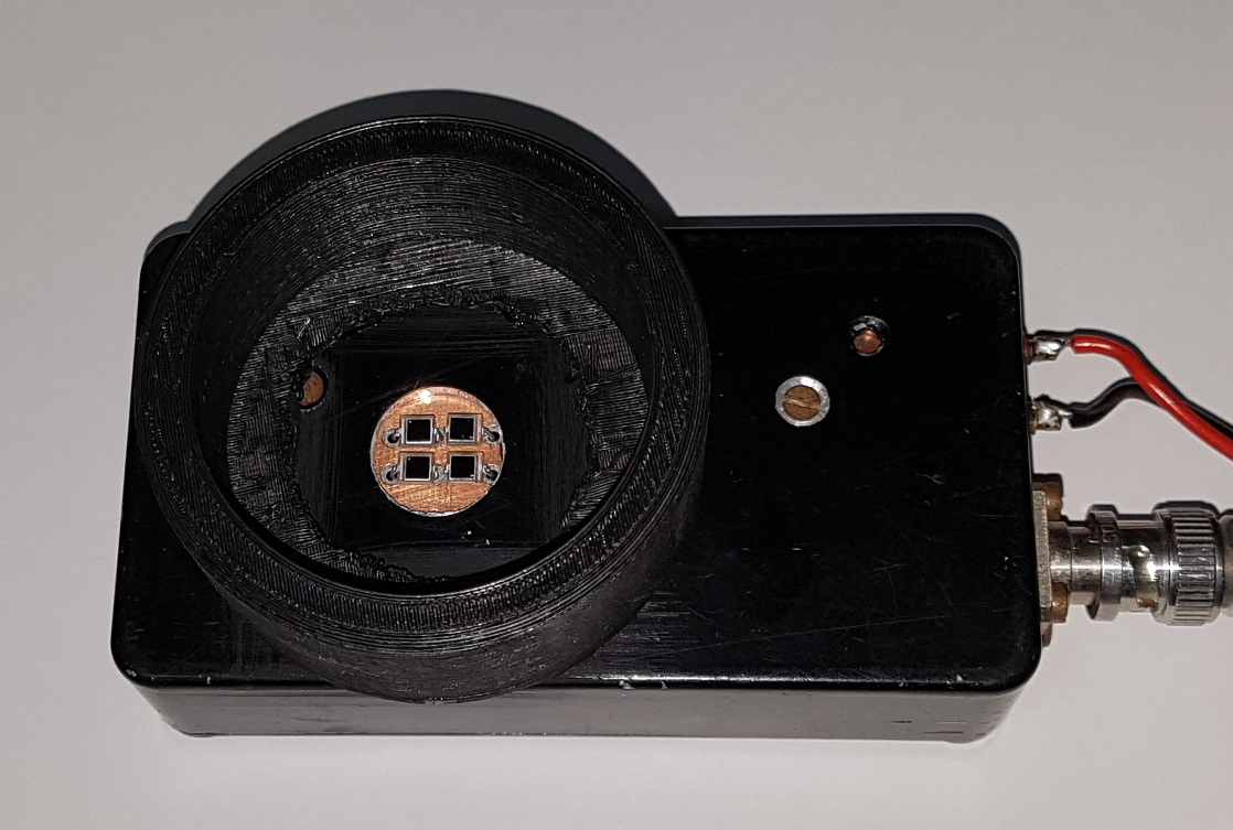
Most of the tests in the following sections are done using the array of 4 BPW34's beheind the 25cm fresnel lens.
Up to now I have not noticed much improvement between the single and 4 photodiode array during the NLOS tests, maybe 1-2dB but it's hard to tell on a weak signal!
I setup a tube in the shack about 2m long with an LED at one end driven by my function generator, the other end of the tube was where I fitted the different receivers for testing.
The 4x BPW34 Rx does give roughly the 6dB of improvement over the single BPW34, there is lots of measurement error in my test setup so the result are not very accurate but shows the improvement is there.
Information on the photodiode array is here https://www.reast.asn.au/wp-content/uploads/2016/08/Optical-VK7MO_VK7TW_VK7DY_Multi_Photodiode_200711.pdf
Future improvement I can make are likely to be a larger Fresnel lens, then more tests with the Rx diode array.
I don't think I'm going to go the expense of using Avalanche Photodiodes unless there is some real interest from Dx stations!!
Tx System
Tests


