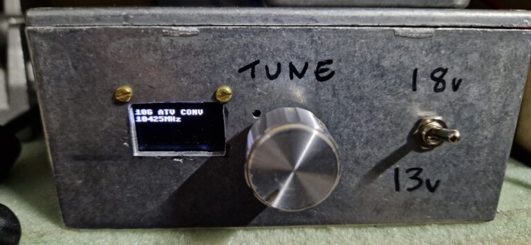
logo


Cluster Activity

Spots per uW band today:
UK spotter or spotted only.

Solar data:
SFI
177
A-Index
5
K-Index
3
Exp.K
0
Sunspots
127
Activity
act
GMF
qui
Aurora?
no

My Weather

ArrayDate:19/03/24 Time:05:12
Temp:11C
Wind Speed:22.5mph
Wind Dir:202deg
Pressure:1004.15mB
Humidity:110%
Dew Point:13C
UKHASnet
Microsource YIG Synth

Now that the source of Elcom synthesisers has nearly dried up i was looking for something else compatable...

There are a few versions of the Microsource YIG Synthesiser available, spec is 10.575-13.35GHz.
I bought a SNP101341001 model.

Reading on other sites i found that this range is not actually available through the regular programming method with G4FRE code, only the 11.2-12GHz range is accepted when programmed.

I decided to have a look into how this module works and try to get it working outside of this range.

Here are a few photos of the board..

PCB Top


PCB Bottom


Basically the PIC is used to interface with external controls as we have seen in the Elcom Synths.
There is a Digital Potentiometer (DS1867) to trim the Reference oscillator - this maybe handy later.
The PLL is a Qualcom Q3236, used in Parallel programming mode.

Power rails appear to be as described elsewhere for the D15 socket:
Pin 15:+8v
Pin 7: +12v - This needs to be a regulated 12v unlike the Elcom units.
Pin 8: Ground
Pin 3: Data
Pin 10:Clock
Pin 11:Load


My initial inspection of the top side only revealed that there were no direct connections from the PLL to the PIC so how was it programmed???
After removing the board from the enclosure i found an Altera CPLD attached directly below the PLL, this was the interface between the PLL and PIC.
The next stage was to try map the pins from the PLL, this was not that productive really as most of them went directly to the CPLD and we know nothing about what it's doing inside, one find was that there were three lines going from the CPLD to the PIC, great ;-)

Now i know what is wired to where i started to look at the comms from the PIC to the CPLD...
Programming a known frequency in with the G4FRE code was useful here, i eventually identified that in between Integer values of the A register the frequency would change, this was because the CPLD was using PWM on the register bits to achieve Fractional N functionality, cool!

The SPI like data from the PIC to the CPLD turned out to be a 12 bit word, at first i had no idea how it was broken down but i knew it must have PLL register values there somewhere...

From MSB to LSB:
Top 3 bits are the M register - reduced range available.
Next 4 bits are the A register
Last 5 bits are the Fractional value range=0-24 (80/24=3.333)

Each A register step is 80MHz.
Each Fractional step is roughly 3.333MHz.
The R register is fixed in CPLD code to 4 (10MHz PLL Comparison freq)

Altering the R register by manually wiring the bits does not gain much because we only have access to 4 bits of the M register through the CPLD, it will be much more work to directly program the PLL and then we would need to create the PWM Fractional part ourselves.

So after all this we now have the same frequency resolution as the original programming method!!

The big difference here is that we can get PLL lock beyond 11.2-12GHz range, the new maximum range is 9.4-13.2GHz.

Using the unit towards the extremes of this range will most likely stress the YIG more than usual, i have no experience with YIG's so tread with caution here!!
For round number steps the best possible is 20MHz due to the limited way the CPLD controls the PLL.

Setting Even fractional values moves 1.666MHz above last value.
Setting Odd fractional values moves 5MHz above last value.
e.g Fractional=1 gives 5MHz shift, Fractional=2 gives 6.666MHz, Fractional=3 gives 11.666MHz.

Example Arduino Nano Code V1

To connect direct to the CPLD you need to lift pins 22,23 and 24 on the PIC and then solder wires to the pads they were soldered to.
22=Data
23=Clock
24=Load

I have tried to compare the Phase noise of an Elcom DFS-1101 and the Microsource unit, the results are very similar.
This measurement was done by using my HB8341 Synth as an LO into a Mixer at 11GHz, the Elcom and Microsource were connected to the mixer and set to 11.2GHz, the resulting 200MHz was measured using an Airspy sdr.
The spurs seen on the Microsource were most likely because i'm not using a regulated +12v rail.

Elcom DFS-1101

Microsource


Last page added:25/03/00 18:32
M0DTS.co.uk