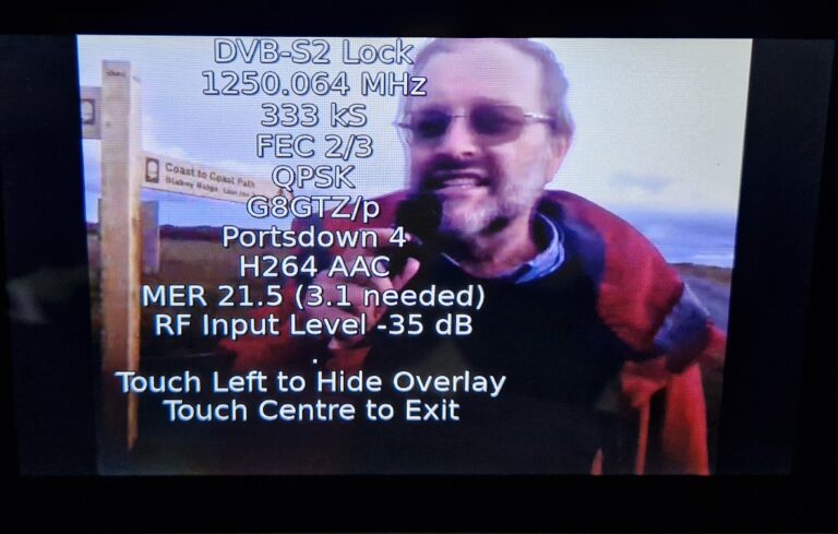
This evening I had a contact with Noel G8GTZ...
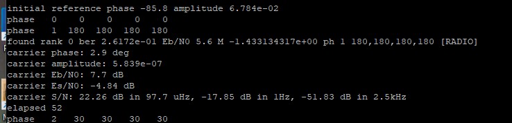
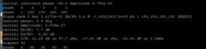
Bernd was sending some signals on VLF again. Same...
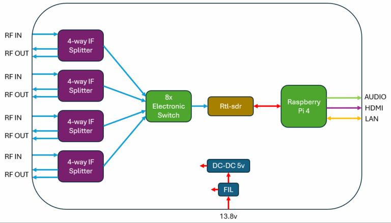
Many years ago i build an SDR Display for...

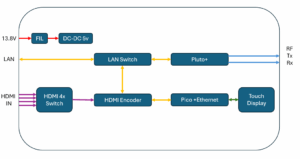
A while back when i started operating on QO100...

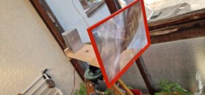
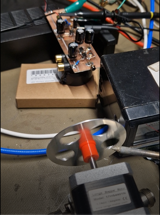
I found another lens in my optical parts box,...

Now I had it sort of working I needed...
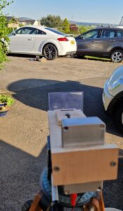
I’ve found myself tinkering somewhere between the high GHz...
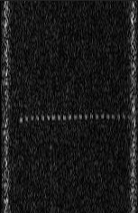
Beacon re-deployed again yesterday evening. Steady signal overnight, around...
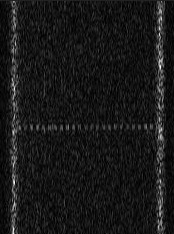
Stable but weaker overnight, clear and down just below...
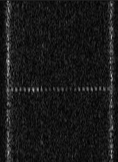
Changes in temperature visible by slight frequency variations! No...