134GHz
So another new band has appeared on my site :-)
The small components used and frequency measurements involved are quite hard to achieve but it is possible!
This band is going to be short range line of sight operation, having enough Tx power or Rx sensitivity for anything else is likely not possible at this time, there is little commercial activity at these frequencies yet.
Typical Tx power is normally 1mW or less, this is achieved by driving a high frequency diode with a few hundred milliwatts at around 33GHz, the multiplication of the LO is 4 times.
Basically you want as low multiplication as possible to achieve best results, x4 is currently the lowest possible multiplication where we have modules available to generate enough power to drive the diodes for Tx.
Best Rx performance is achieved using an anti-parallel diode as the harmonic mixer but this is not useful for Tx.
Tx is usually just the LO signal On/Off Morse or FM modulated. We can do SSB by mixing with an IF but the mixing loss would be some 10dB down on the 134GHz harmonic itself so not idea for longer path tests, i do plan to try this though eventually with a Digital ATV signal to see if it is possible...
More than likely though it will be easier to do FM ATV by modulating the 11GHz source.
The system consists of an Elcom DFS-1101 programmable synthesiser which generates the initial 11GHz signal.
This signal then feeds into the normal LO port of the Broadern transceiver.
The Broadern unit has a LO multiplier inside and all we do is bias the mixer to allow the multiplied LO signal to leak through into the later Tx power amplifier devices and achieved up to about 1 watt of RF at 33GHz.
We have to be careful here to limit this power as 1 watt will destroy the diode very easily!
Below is photo of the initial test setup.
The Elcom 11GHz source is at the back.
The Broadern unit is the square flat silver module acting as the x3 multiplier and amplifier.
The high frequency diode is enclosed with the pcb inside the metal block on the end of the waveguide at the Broadern Tx output.
The Rx IF comes out of the SMA connector.
Power supply is on the Right, 3x LM2596 DC-DC converters for +5V,+10V and -12V.
To generate a (VERY!) weak signal at 134GHz I'm using my signal generator at +10dBm into a GaAsFet soldered across the end of some semi rigid coax.
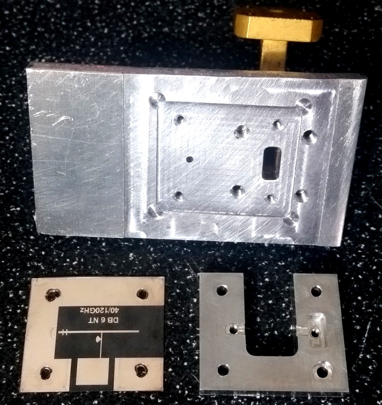
The 134GHz part is just the DB6NT pcb #47 with a diode attached, current setting adjustment and a connection for the Rx IF.
I milled my own metalwork for this in two pieces, the diode is epoxied in at one end directly over the 1.6mm hole in the metal, the 33GHz LO signal is fed in at the end of the track through the larger WR28 waveguide port.
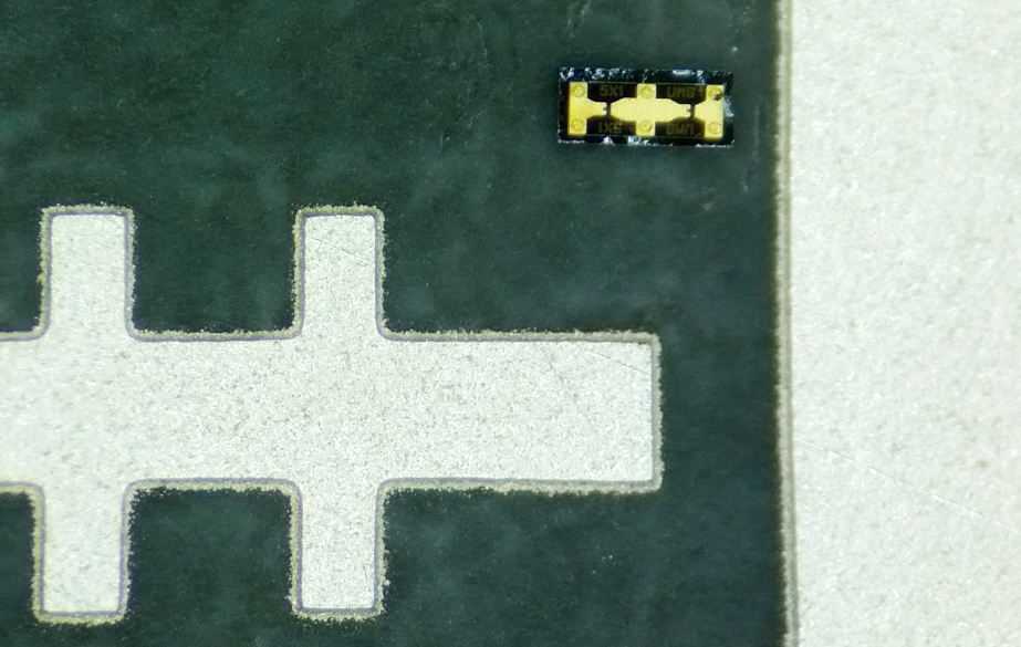
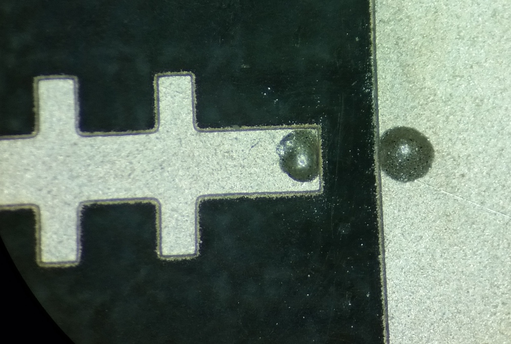
Here are some photos of the metalwork of the high frequency part and Epoxying of the tiny diode (in this case DBES105A):
Epoxy used is 3 year old CW2400 which has been stored at room temp.. surprisingly it still cures very well!


.jpg)


